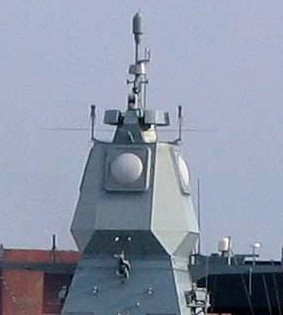
APAR AESA onboard Hamburg (F220), a Sachsen-class frigate of the German Navy
An active electronically scanned array (AESA), also known as active phased array radar (APAR), is a type of phased array radar whose transmitter and receiver functions are composed of numerous small solid-state transmit/receive modules (TRMs). AESA radars aim their "beam" by emitting separate radio waves from each module that interfere constructively at certain angles in front of the antenna. Advanced AESA radars can improve on the older passive electronically scanned array (PESA) radars by spreading their signal emissions out across a band of frequencies, which makes it very difficult to detect over background noise, allowing ships and aircraft to broadcast powerful radar signals while still remaining stealthy.
Basic concept[]
Radar systems generally work by connecting an antenna to a powerful radio transmitter to emit a short pulse of signal. The transmitter is then disconnected and the antenna is connected to a sensitive receiver which amplifies any echos from target objects. By measuring the time it takes for the signal to return, the radar receiver can determine the distance to the object. The receiver then sends the resulting output to a display of some sort. The transmitter elements were typically klystron tubes or magnetrons, which are suitable for amplifying or generating a narrow range of frequencies to high power levels. To scan a portion of the sky, the radar antenna must be physically moved to point in different directions.
Starting in the 1960s new solid-state devices capable of delaying the transmitter signal in a controlled way were introduced. That led to the first practical large-scale passive electronically scanned array, or simply phased array radar. PESAs took a signal from a single source, split it into hundreds of paths, selectively delayed some of them, and sent them to individual antennas. The radio signals from the separate antennas overlapped in space, and the interference patterns between the individual signals was controlled to reinforce the signal in certain directions, and mute it in all others. The delays could be easily controlled electronically, allowing the beam to be steered very quickly without moving the antenna. A PESA can scan a volume of space much quicker than a traditional mechanical system. Additionally, thanks to progress in electronics, PESAs added the ability to produce several active beams, allowing them to continue scanning the sky while at the same time focusing smaller beams on certain targets for tracking or guiding semi-active radar homing missiles. PESAs quickly became widespread on ships and large fixed emplacements in the 1960s, followed by airborne sensors as the electronics shrank.
AESAs are the result of further developments in solid-state electronics. In earlier systems the transmitted signal was originally created in a klystron or traveling wave tube or similar device, which are relatively large. Receiver electronics were also large due to the high frequencies that they worked with. The introduction of gallium arsenide microelectronics through the 1980s served to greatly reduce the size of the receiver elements, until effective ones could be built at sizes similar to those of handheld radios, only a few cubic centimeters in volume. The introduction of JFETs and MESFETs did the same to the transmitter side of the systems as well. Now an entire radar, the transmitter, receiver and antenna, could be shrunk into a single "transmitter-receiver module" (TRM) about the size of a carton of milk.
The primary advantage of an AESA over a PESA is capability of the different modules to operate on different frequencies. Unlike the PESA, where the signal is generated at single frequencies by a small number of transmitters, in the AESA each module generates and radiates its own independent signal. This allows the AESA to produce numerous "sub-beams" and actively "paint" a much larger number of targets. Additionally, the solid-state transmitters are able to transmit effectively at a much wider range of frequencies, giving AESAs the ability to change their operating frequency with every pulse sent out. AESAs can also produce beams that consist of many different frequencies at once, using post-processing of the combined signal from a number of TRMs to re-create a display as if there was a single powerful beam being sent.
Advantages[]
AESAs add many capabilities of their own to those of the PESAs. Among these are: the ability to form multiple beams, to use each TRM for different roles concurrently, like radar detection, and, more importantly, their multiple simultaneous beams and scanning frequencies create difficulties for traditional, correlation-type radar detectors.
Low probability of intercept[]
Radar systems work by sending out a signal and then listening for its echo off distant objects. Each of these paths, to and from the target, is subject to the inverse square law of propagation. That means that a radar's received energy drops with the fourth power of the distance, which is why radar systems require high powers, often in the megawatt range, to be effective at long range.[1]
The radar signal being sent out is a simple radio signal, and can be received with a simple radio receiver. It is common to use such a receiver in the targets, normally aircraft, to detect radar broadcasts. Unlike the radar unit, which must send the pulse out and then receive its reflection, the target's receiver does not need the reflection and thus the signal drops off only as the square of distance. This means that the receiver is always at an advantage [neglecting disparity in antenna size] over the radar in terms of range - it will always be able to detect the signal long before the radar can see the target's echo. Since the position of the radar is extremely useful information in an attack on that platform, this means that radars generally must be turned off for lengthy periods if they are subject to attack; this is common on ships, for instance.
Turning that received signal into a useful display is the purpose of the "radar warning receiver" (RWR). Unlike the radar, which knows which direction it is sending its signal, the receiver simply gets a pulse of energy and has to interpret it. Since the radio spectrum is filled with noise, the receiver's signal is integrated over a short period of time, making periodic sources like a radar add up and stand out over the random background. The rough direction can be calculated using a rotating antenna, or similar passive array using phase or amplitude comparison. Typically RWRs store the detected pulses for a short period of time, and compare their broadcast frequency and pulse repetition frequency against a database of known radars. The direction to the source is normally combined with symbology indicating the likely purpose of the radar - airborne early warning, surface to air missile, etc.
This technique is much less useful against AESA radars. Since the AESA (or PESA) can change its frequency with every pulse (except when using doppler filtering), and generally does so using a pseudo-random sequence, integrating over time does not help pull the signal out of the background noise. Moreover, AESA radars may extend the duration of the pulse and lower their peak power. This makes no difference to the total energy reflected by the target but makes the detection of the pulse by an RWR system less likely.[2] Nor does the AESA have any sort of fixed pulse repetition frequency, which can also be varied and thus hide any periodic brightening across the entire spectrum. Older generation RWRs are essentially useless against AESA radars, which is why AESA's are also known as 'low probability of intercept radars. Modern RWRs must be made highly sensitive (small angles and bandwidths for individual antennas, low transmission loss and noise)[2] and add successive pulses through time-frequency processing to achieve useful detection rates.[3]
High jamming resistance[]
Jamming is likewise much more difficult against an AESA. Traditionally, jammers have operated by determining the operating frequency of the radar and then broadcasting a signal on it to confuse the receiver as to which is the "real" pulse and which is the jammer's. This technique works as long as the radar system cannot easily change its operating frequency. When the transmitters were based on klystron tubes this was generally true, and radars, especially airborne ones, had only a few frequencies to choose among. A jammer could listen to those possible frequencies and select the one to be used to jam.
Most radars using modern electronics are capable of changing their operating frequency with every pulse. An AESA has the additional capability of spreading its frequencies across a wide band even in a single pulse, a technique known as a "chirp". This can make jamming less effective; although it is possible to send out broadband white noise against all the possible frequencies, this reduces the amount of jammer energy in any one frequency. In fact, AESAs can then be switched to a receive-only mode, and use these powerful jamming signals instead to track its source, something that required a separate receiver in older platforms. By integrating received signals from the targets' own radar along with a lower rate of data from its own broadcasts, a detection system with a precise RWR like an AESA can generate more data with less energy. Some beamforming-capable systems, usually ground-based, may even discard a transmitter entirely.
However, using a single receiving antenna only gives a direction. Obtaining a range and a target vector requires at least two physically separate passive devices for triangulation to provide instantaneous determinations, unless phase interferometry is used. Target motion analysis can estimate these quantities by incorporating many directional measurements over time, along with knowledge of the position of the receiver and constraints on the possible motion of the target.
Other advantages[]
Since each element in an AESA is a powerful radio receiver, active arrays have many roles besides traditional radar. One use is to dedicate several of the elements to reception of common radar signals, eliminating the need for a separate radar warning receiver. The same basic concept can be used to provide traditional radio support, and with some elements also broadcasting, form a very high bandwidth data link. The F-35 uses this mechanism to send sensor data between aircraft in order to provide a synthetic picture of higher resolution and range than any one radar could generate. In 2007, tests by Northrop Grumman, Lockheed Martin, and L-3 Communications enabled the AESA system of a Raptor to act like a WiFi access point, able to transmit data at 548 megabits per second and receive at gigabit speed; this is far faster than the Link 16 system used by US and allied aircraft, which transfers data at just over 1 Mbit/s.[4] To achieve these high data rates requires a highly directional antenna which AESA provides but which precludes reception by other units not within the antennas beamwidth. Like most Wi-Fi designs, Link-16 transmits its signal omni-directionally to ensure all units within range can receive the data.
AESAs are also much more reliable than either a PESA or older designs. Since each module operates independently of the others, single failures have little effect on the operation of the system as a whole. Additionally, the modules individually operate at low powers, perhaps 40 to 60 watts, so the need for a large high-voltage power supply is eliminated.
Replacing a mechanically scanned array with a fixed AESA mount (such as on the F/A-18E/F Super Hornet) can help reduce an aircraft's overall radar cross-section (RCS), but some designs (such as the Eurofighter Typhoon) forgo this advantage in order to combine mechanical scanning with electronic scanning and provide a wider angle of total coverage.[5]
Limitations[]
The highest Field of View (FOV) for a flat phased array antenna is currently 120°, however this can be combined with mechanical steering as noted above.[6]
List of existing systems[]
History[]
The first military ground-based AESA was the J/FPS-3 which became fully operational with the 45th Aircraft Control and Warning Group of the Japan Self-Defense Forces in 1995.
The first series production ship-based AESA was the OPS-24 Fire-control radar introduced on the Asagiri-class destroyer DD-155 Hamagiri launched in 1988.[7]
The first airborne series production AESA was the EL/M-2075 Phalcon on a Chilean Air Force Boeing 707 that entered service in 1994.
The first AESA on a combat aircraft was the J/APG-1 introduced on the Mitsubishi F-2 in 1995.[8]
The first AESA on a missile is the seeker head for the AAM-4B air-to-air missile (Mitsubishi F-2, Mitsubishi F-15J).[8]
US based manufacturers of the AESA radars used in the F22 and Super Hornet include Northrop Grumman[9] and Raytheon.[10] These companies also design, develop and manufacture the transmit/receive modules which comprise the 'building blocks' of an AESA radar. The requisite electronics technology was developed in-house via Department of Defense research programs such as MIMIC Program.[11][12]
Airborne systems[]
- Northrop Grumman
- AN/APG-77, for the F-22 Raptor
- AN/APG-80, for the F-16E/F Desert Falcon
- AN/APG-81, for the F-35 Lightning II
- AN/APY-9, for the E-2D Advanced Hawkeye
- Multirole AESA, for the Boeing Wedgetail (AEW&C)
- AN/ASQ-236 Podded AESA Radar
- AN/ZPY-1 STARLite Small Tactical Radar - Lightweight, for manned and unmanned aircraft
- AN/ZPY-2 Multi-Platform Radar Technology Insertion Program (MP-RTIP)
- AN/ZPY-3 Multi-Function Active Sensor (MFAS) for MQ-4C Triton
- SABR, for F-16 Fighting Falcon upgrades
- 3DELRR Three-Dimensional Expeditionary Long-Range Radar
- Vehicle Dismount and Exploitation Radar (VADER)
- Raytheon
- AN/APG-63(V)2 and AN/APG-63(V)3, for the F-15C Eagle, Republic of Singapore's F-15SG
- AN/APG-79, for the F/A-18E/F Super Hornet and EA-18G Growler
- AN/APG-82(V)1 for the F-15E Strike Eagle
- AN/APQ-181 upgrade from PESA to AESA, for Northrop Grumman B-2 Spirit bomber
- RACR (Raytheon Advanced Combat Radar)
- AAS Advanced Airborne Sensor (AESA follow-on to the Littoral Surveillance Radar System (LSRS, APS-149 also built by Raytheon), for the Boeing P-8 Poseidon
- Raytheon Sentinel ASTOR (Airborne STand-Off Radar)
- Captor-E CAESAR (CAPTOR Active Electronically Scanning Array Radar)
- RBE2-AA Radar à Balayage Electronique 2 - Active Array
- SELEX
- Seaspray 5000E
- Seaspray 7000E, for helicopters
- Seaspray 7500E for General Atomics MQ-9 Reaper
- Vixen 500E
- Vixen 1000E
- Raven ES-05 AESA for the JAS-39E Gripen NG[13]
- PicoSAR
- Mitsubishi Electric Corporation
- J/APG-1 / J/APG-2 AESA for the Mitsubishi F-2 fighter
- HPS-104 for the Mitsubishi SH-60
- Multifunction RF Sensor for Mitsubishi ATD-X
- Toshiba
- HPS-106, air & surface search radar, for the Kawasaki P-1 maritime patrol aircraft, four antenna arrays.
- Ericsson
- Erieye AEW&C
- PS-05/A MK-5 for JAS 39 Gripen.
- EMB 145 AEW&C
- Phazotron NIIR
- Tikhomirov NIIP
- N036 Byelka, for Sukhoi T-50
- Elta
- EL/M-2083 aerostat-mounted air search radar
- EL/M-2052, for fighters. Interim candidate for HAL Tejas. Also, suitable for F-15, MiG-29 & Mirage 2000
- EL/M-2075 radar for the IAI Phalcon AEW&C system
- EL/W-2085 advanced version of the radar for the EL/M-2075, used on the Gulfstream G550
- EL/W-2090 similar to the EL/W-2085, only used on the Ilyushin Il-76
- NRIET (Nanjing Research Institute of Electronic Technology/14 institute) designed radars for
- KJ-2000 AEW&C system[14]
- KJ-200[14]
- ZDK-03
- Various Y-8 variants
- Y-7 AWACS
- J-16
- Shenyang J-31
- Chengdu J-20 (Type 1475 Radar)
- JF-17 Thunder (Block II/III)
- Chengdu J-10B[15]
- Shenyang J-15
- Shenyang J-11B
- Z-8AEW
Ground and Maritime based systems[]
- APAR (active phased array radar): Thales' multifunction radar is the primary sensor of the Royal Netherlands Navy's De Zeven Provinciën class frigates, the German Navy's Sachsen class frigates, and the Royal Danish Navy's Ivar Huitfeldt class frigates. APAR is the first active electronically scanned array multifunction radar employed on an operational warship.[16]
- BÜR - Bodenüberwachungsradar by Airbus Group, for the Bundeswehr
- BAE Systems Type 997 Artisan 3D
- Cassidian
- TRS-4D
- COBRA Counter-battery radar
- Elta
- EL/M-2080 Green Pine ground-based early warning AESA radar
- EL/M-2106 ATAR air defense fire control radar
- EL/M-2180 - WatchR Guard Multi-Mode Staring Ground Surveillance Radar
- EL/M-2248 MF-STAR multifunction naval radar
- EL/M-2258 Advanced Lightweight Phased Array ALPHA multifunction naval radar
- EL/M-2084 multimission radar (artillery weapon location, air defence and fire control)
- EL/M-2133 WindGuard - Trophy active protection system radar
- Lockheed Martin AN/TPQ-53 Counterfire Target Acquisition Radar
- Northrop Grumman
- AN/TPS-80 Ground/air task-oriented radar (G/ATOR)
- HAMMR Highly Adaptable Multi-Mission Radar
- RADA Electronic Industries[17]
- RPS-10
- RPS-15
- RPS-40
- RPS-42
- RHS-44
- Raytheon
- FlexDAR Flexible Distributed Array Radar
- U.S. National Missile defense Sea-based X-band Radar (XBR)
- AN/SPY-3 multifunction radar for U.S. DD(X) and CVN-21 next-generation surface vessels
- Dual Band Radar for U.S. Gerald R. Ford-class aircraft carrier and Zumwalt-class destroyer next-generation surface vessels
- Cobra Judy Replacement (CJR)/Cobra King on USNS Howard O. Lorenzen (T-AGM-25)
- AN/FPS-132 Upgraded Early Warning Radar UEWR (PAVE PAWS upgrade from PESA to AESA)
- Saab Group GIRAFFE Radar: GIRAFFE 1X, GIRAFFE 4A, GIRAFFE 8A[18]
- Selex
- CBAAR C-Band Active Array Radar
- KRONOS 3D multi-function radar
- RAN-40L 3D EWR
- ThalesRaytheonSystems
- Thales
- Sea Fire 500 on FREMM-ER frigates
- Sea Master 400
- Sea Watcher 100
- MEADS's fire control radar
- Type H/LJG-346(8) on Chinese aircraft carrier Liaoning
- Type 348 Radar on Type 052C destroyer
- AESA radar on Type 052D destroyer
- H/LJG-346 SAPARS (Predecessor to the Type 348 Radar on Type 052C destroyer)
- Type 305A Radar (Acquisition radar for the HQ-9 missile system)[19]
- YLC-2 Radar[20]
- THAAD system fire control radar
- Type 3 Chū-SAM Medium Range Surface-to-Air MissileSystem (Chu-SAM,SAM-4) multifunction radar
- BAE Systems Insyte SAMPSON multifunction radar for UK Type 45 destroyers
- OPS-24 Mitsubishi Electric Corporation (The world's first Naval Active Electronically Scanned Array radar) on Asagiri-class destroyers, Murasame-class destroyer (1994) and Takanami-class destroyers
- OPS-50 (FCS-3) Mitsubishi Electric Corporation (Melco) on the Hyūga-class helicopter destroyer, Izumo-class helicopter destroyer and Akizuki-class destroyer (2010)
- J/FPS-3 Japanese main ground-based air defense radar produced by Melco
- J/FPS-4 Cheaper than J/FPS-3, produced by Toshiba
- J/FPS-5 Japanese ground-based next-generation missile defense radar
- J/TPS-102 Self-propelled ground-based radar, cylindrical array antenna, NEC
- JMPQ-P13 Counter-battery radar, Toshiba
- JTPS-P14 Transportable air defence radar, Melco
- JTPS-P16 Firefinder radar, Melco
- CEA Technologies A 4th generation multifunction digital active phased array radar, installed on HMAS Perth and to be installed on all ANZAC class frigates.
- NNIIRT 1L119 Nebo SVU mobile AESA 3-dimensional surveillance radar
- VNIIRT Gamma DE mobile 3-dimensional solid-state AESA surveillance radar
- 50N6A multifunctional radar of the Vityaz missile system and 42S6 «Morfey» («Morpheus»)
- Multi-function radar of the KM-SAM
See also[]
- Radar configurations and types
- Receiver
- Passive electronically scanned array
- Low Probability of Intercept Radar
References[]
- ↑ The ABCs of Radar
- ↑ 2.0 2.1 http://ieeetmc.net/r5/dallas/aes/IEEE-AESS-Nov04-Wiley.pdf
- ↑ http://www.emrsdtc.co.uk/conferences/2004/downloads/pdf/tech_conf_papers/A14.pdf
- ↑ Page, Lewis. "F-22 superjets could act as flying Wi-Fi hotspots." The Register, 19 June 2007. Retrieved: 7 November 2009.
- ↑ F/A-18 AESA - New Technology Revolutionizes Radar Benefits
- ↑ Physical limitation of the maximum swivel angle of an AESA
- ↑ Tomohiko Tada (March 2010). "4. Radar/ECM/ESM (Shipboard weapons of JMSDF 1952-2010)" (in Japanese). Kaijin-sha. pp. 100–105.
- ↑ 8.0 8.1 Japan Upgrading 60 F-2s With AAM-4, J/APG-2
- ↑ Northrop Grumman Successfully Completes F-22 Radar Flight-Test Certification
- ↑ Raytheon Company: Products & Services: AESA Technology
- ↑ A DARPA Perspective on the Future of Electronics
- ↑ http://www.ll.mit.edu/news/journal/pdf/vol12_no2/12_2devphasedarray.pdf
- ↑ http://www.saabgroup.com/en/Air/Gripen-Fighter-System/Gripen-and-Switzerland/The-Gripen-Solution/AESA-radar/
- ↑ 14.0 14.1 http://www.ausairpower.net/APA-PLA-AWACS-Programs.html PLA-AF Airborne Early Warning & Control Programs
- ↑ http://cnair.top81.cn/J-10_J-11_FC-1.htm#j-10b Chinese Military Aviation - Fighters (Cont.)
- ↑ Jane's Navy International, August 2010, "Expanding coverage from sea to sky"
- ↑ http://www.rada.com/capabilities-3/land-radars-2.html RADA Tactical Land Radars
- ↑ http://www.janes.com/article/38219/saab-expands-surface-radar-portfolio Saab expands surface radar portfolio
- ↑ http://www.ausairpower.net/APA-HQ-9-12-Battery-Radars.html HQ-9 and HQ-12 SAM system battery radars
- ↑ PLA Air Defence Radars
External links[]
- Active Electronically Steered Arrays – A Maturing Technology
- FLUG REVUE December 1998: Modern fighter radar technology
- Phased Arrays and Radars – Past, Present and Future
The original article can be found at Active electronically scanned array and the edit history here.